


STP ( Spanning tree protocol )
Switching Loops
A Layer-2 switch belongs to only one broadcast domain, and will forward both broadcasts and multicasts out every port but the originating port. When a switching loop is introduced into the network, a destructive
broadcast storm will develop within seconds. A storm occurs when broadcasts are endlessly forwarded through the loop. Eventually, the storm will choke off all other network traffic.

If HostA sends out a broadcast, SwitchD will forward the broadcast out all ports in the same VLAN, including the trunk ports connecting to SwitchB and SwitchE. In turn, those two switches will forward that broadcast out all ports, including the trunks to the neighboring SwitchA and SwitchC. The broadcast will loop around the switches infinitely. In fact, there will be two separate broadcast storms cycling in opposite directions through the switching loop. Only powering off the switches or physically removing the loop will stop the storm.
Spanning Tree Protocol (STP) was developed to prevent the broadcast storms caused by switching loops. STP was originally defined in IEEE 802.1D. Switches running STP will build a map or topology of the entire switching network. STP will identify if there are any loops, and then disable or block as many ports as necessary to eliminate all loops in the topology. A blocked port can be reactivated if another port goes down. This allows STP to maintain redundancy and fault-tolerance. However, because ports are blocked to eliminate loops, STP does not support load balancing unless an EtherChannel is used. EtherChannel is
covered in great detail in another guide.
STP switches exchange Bridge Protocol Data Units (BPDU’s) to build the topology database. BPDU’s are forwarded out all ports every two seconds, to a dedicated MAC multicast address of 0180.c200.0000.
Building the STP topology is a multistep convergence process:
• A Root Bridge is elected
• Root ports are identified
• Designated ports are identified
• Ports are placed in a blocking state as required, to eliminate loops
STP is enabled by default on all Cisco switches, for all VLANs.
Electing an STP Root Bridge
The first step in the STP convergence process is electing a Root Bridge, which is the central reference point for the STP topology. As a best practice, the Root Bridge should be the most centralized switch in the STP topology. A Root Bridge is elected based on its Bridge ID, comprised of two components in the original 802.1D standard:
• 16-bit Bridge priority
• 48-bit MAC address
The default priority is 32,768, and the lowest priority wins. If there is a tie
in priority, the lowest MAC address is used as the tie-breaker.

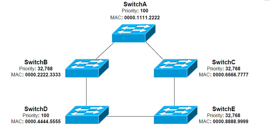
Switches exchange BPDU’s to perform the election process, and the lowest Bridge ID determines the Root Bridge:
• SwitchB, SwitchC, and SwitchE have the default priority of 32,768.
• SwitchA and SwitchD are tied with a lower priority of 100.
• SwitchA has the lowest MAC address, and will be elected the Root
Bridge.
By default, a switch will always believe it is the Root Bridge, until it receives a BPDU from a switch with a lower Bridge ID. This is referred to as a superior BPDU. The election process is continuous – if a new switch with the lowest Bridge ID is added to the topology, it will be elected as the Root Bridge.
A Layer-2 switch belongs to only one broadcast domain, and will forward both broadcasts and multicasts out every port but the originating port. When a switching loop is introduced into the network, a destructive
broadcast storm will develop within seconds. A storm occurs when broadcasts are endlessly forwarded through the loop. Eventually, the storm will choke off all other network traffic.

If HostA sends out a broadcast, SwitchD will forward the broadcast out all ports in the same VLAN, including the trunk ports connecting to SwitchB and SwitchE. In turn, those two switches will forward that broadcast out all ports, including the trunks to the neighboring SwitchA and SwitchC. The broadcast will loop around the switches infinitely. In fact, there will be two separate broadcast storms cycling in opposite directions through the switching loop. Only powering off the switches or physically removing the loop will stop the storm.
Spanning Tree Protocol (STP) was developed to prevent the broadcast storms caused by switching loops. STP was originally defined in IEEE 802.1D. Switches running STP will build a map or topology of the entire switching network. STP will identify if there are any loops, and then disable or block as many ports as necessary to eliminate all loops in the topology. A blocked port can be reactivated if another port goes down. This allows STP to maintain redundancy and fault-tolerance. However, because ports are blocked to eliminate loops, STP does not support load balancing unless an EtherChannel is used. EtherChannel is
covered in great detail in another guide.
STP switches exchange Bridge Protocol Data Units (BPDU’s) to build the topology database. BPDU’s are forwarded out all ports every two seconds, to a dedicated MAC multicast address of 0180.c200.0000.
Building the STP topology is a multistep convergence process:
• A Root Bridge is elected
• Root ports are identified
• Designated ports are identified
• Ports are placed in a blocking state as required, to eliminate loops
STP is enabled by default on all Cisco switches, for all VLANs.
Electing an STP Root Bridge
The first step in the STP convergence process is electing a Root Bridge, which is the central reference point for the STP topology. As a best practice, the Root Bridge should be the most centralized switch in the STP topology. A Root Bridge is elected based on its Bridge ID, comprised of two components in the original 802.1D standard:
• 16-bit Bridge priority
• 48-bit MAC address
The default priority is 32,768, and the lowest priority wins. If there is a tie
in priority, the lowest MAC address is used as the tie-breaker.
Switches exchange BPDU’s to perform the election process, and the lowest Bridge ID determines the Root Bridge:
• SwitchB, SwitchC, and SwitchE have the default priority of 32,768.
• SwitchA and SwitchD are tied with a lower priority of 100.
• SwitchA has the lowest MAC address, and will be elected the Root
Bridge.
By default, a switch will always believe it is the Root Bridge, until it receives a BPDU from a switch with a lower Bridge ID. This is referred to as a superior BPDU. The election process is continuous – if a new switch with the lowest Bridge ID is added to the topology, it will be elected as the Root Bridge.
)
Social Plugin